

Compact Muon Solenoid
LHC, CERN
| CMS-TRK-15-002 ; CERN-EP-2016-320 | ||
| Mechanical stability of the CMS strip tracker measured with a laser alignment system | ||
| CMS Collaboration | ||
| 8 January 2017 | ||
| JINST 12 (2017) P04023 | ||
| Abstract: The CMS tracker consists of 206 m$^2$ of silicon strip sensors assembled on carbon fibre composite structures and is designed for operation in the temperature range from $-25$ to $+25^\circ$C. The mechanical stability of tracker components during physics operation was monitored with a few $\mu$m resolution using a dedicated laser alignment system as well as particle tracks from cosmic rays and hadron-hadron collisions. During the LHC operational period of 2011-2013 at stable temperatures, the components of the tracker were observed to experience relative movements of less than 30$ \mu$m. In addition, temperature variations were found to cause displacements of tracker structures of about 2$\mu$m/$^\circ$C, which largely revert to their initial positions when the temperature is restored to its original value. | ||
| Links: e-print arXiv:1701.02022 [physics.ins-det] (PDF) ; CDS record ; inSPIRE record ; CADI line (restricted) ; | ||
| Figures | |
png pdf |
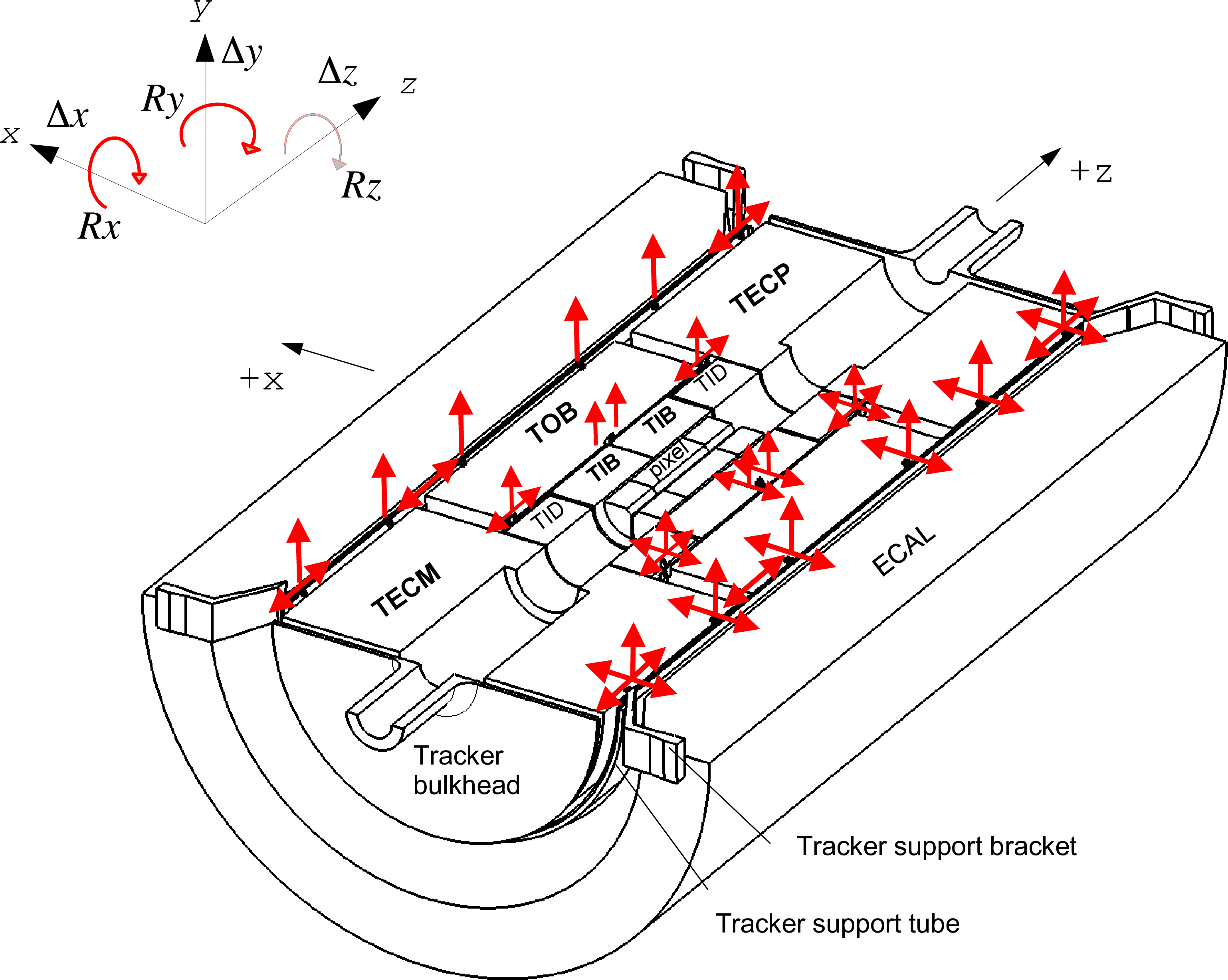
Figure 1:
Mechanical layout and mounting of the tracker subdetectors (bottom half is shown). The TIB+TID are mounted inside the TOB, while the TOB, TECP, and the TECM are mounted inside the TST. The red arrows indicate the connection points and their kinematic constraints. |
png pdf |
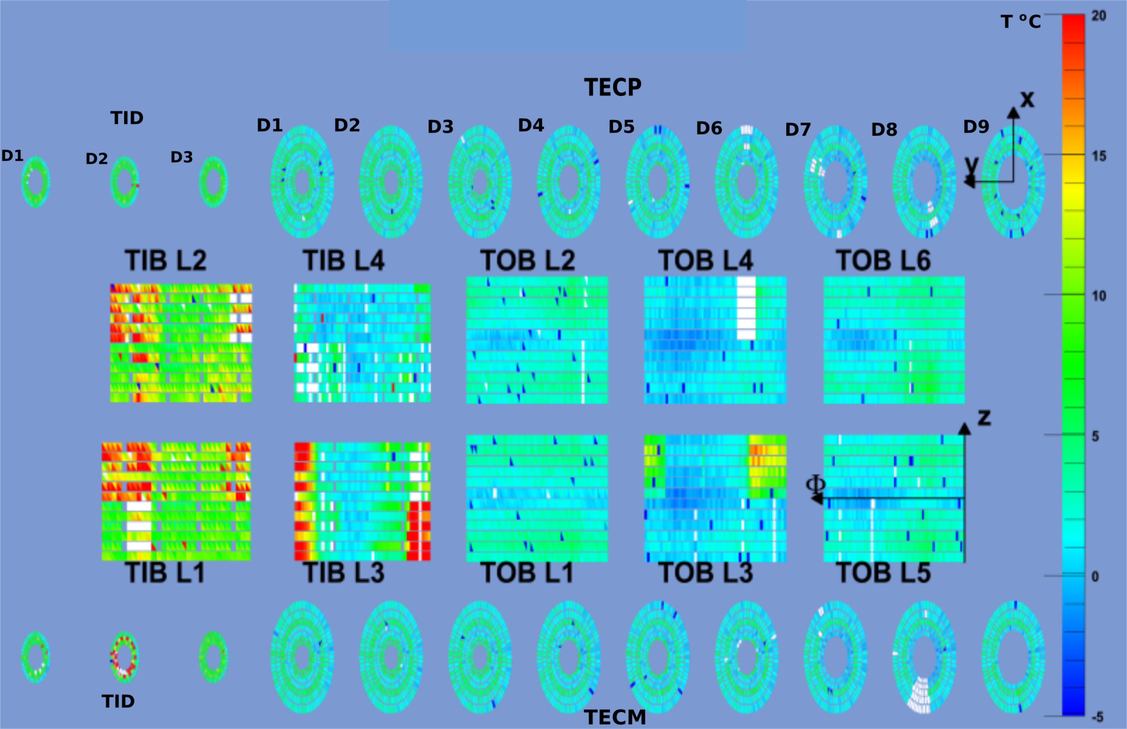
Figure 2:
Example of the temperature distribution, shown as a colour palette ($^\circ $C), measured on silicon sensors in the TIB (L1-L4), TOB layers (L1-L6), and the TEC (D1-D9), TID (D1-D3) disks, with the cooling plant operating at $\mathrm {T} = -5^\circ $C. The white spots correspond to nonoperational detectors, and red spots are the closed cooling loops and bad cooling contacts. |
png pdf |
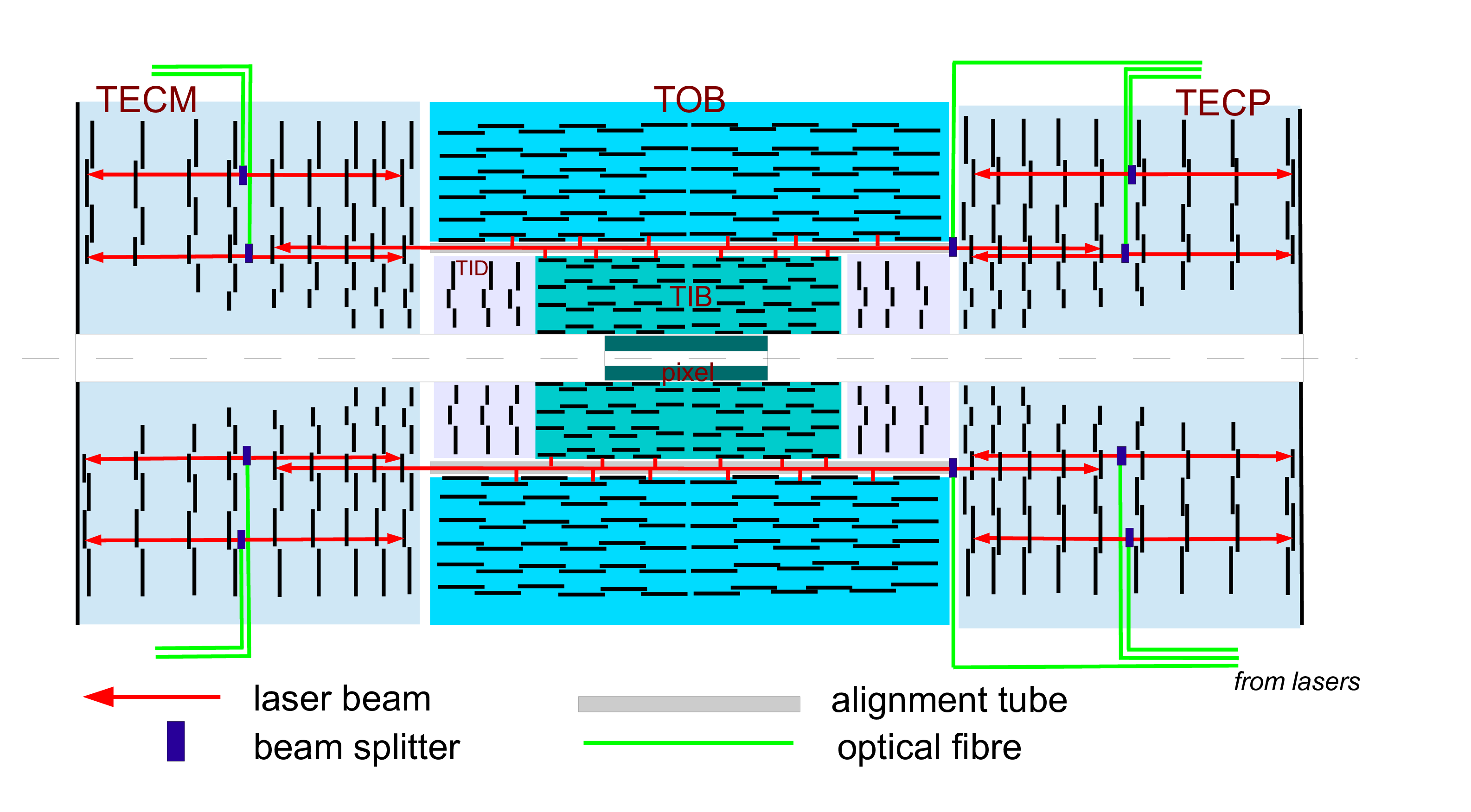
Figure 3:
Distribution of the laser beams in the CMS tracker. The eight laser beams inside the alignment tubes are used for the global alignment of TOB, TIB, and TEC subdetectors. The 32 laser beams in the TECs are used for the internal alignment of TEC disks. |
png pdf |
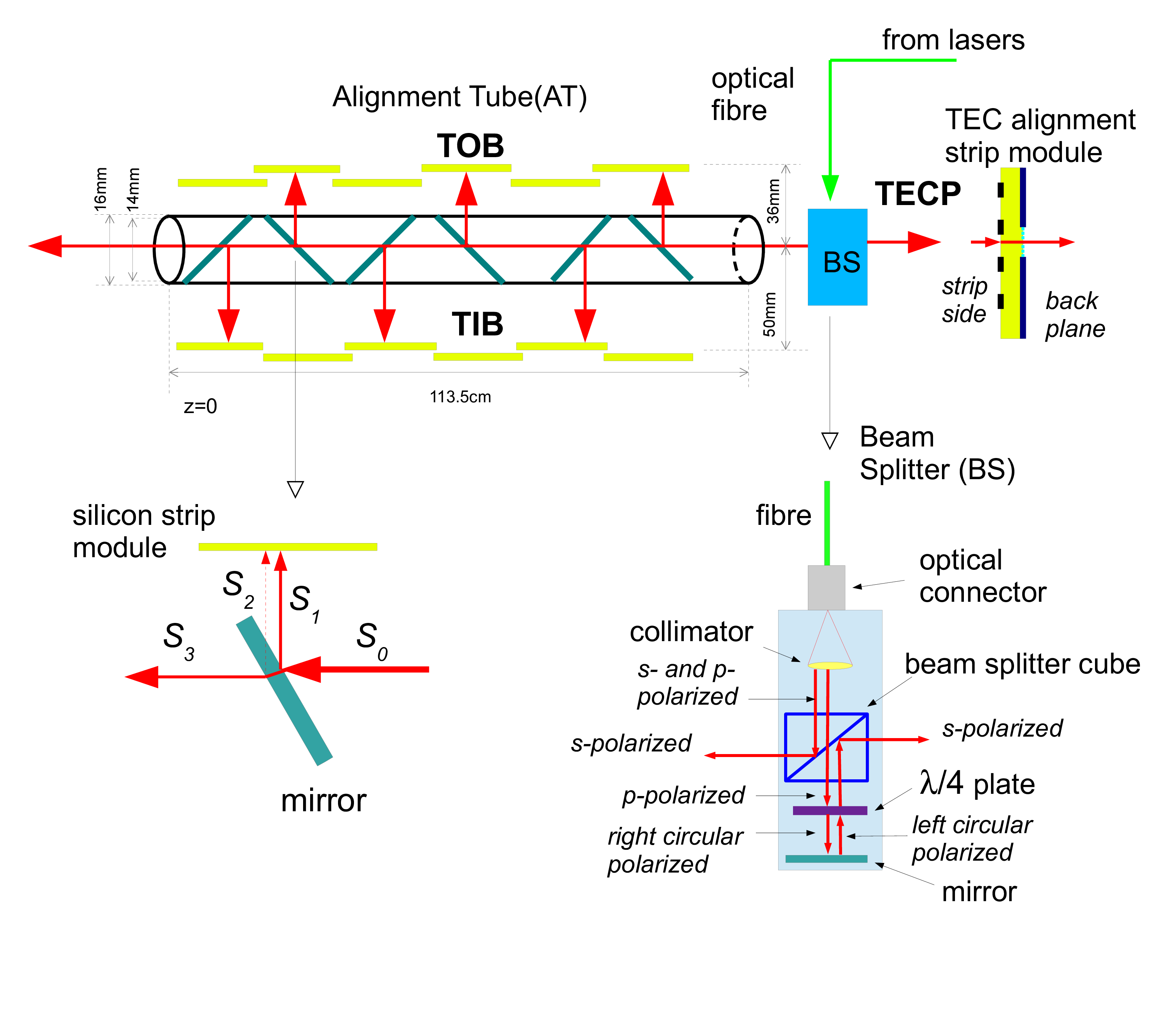
Figure 4:
The LAS components: alignment tube, mirror, and beam splitter. |
png pdf |
Figure 5:
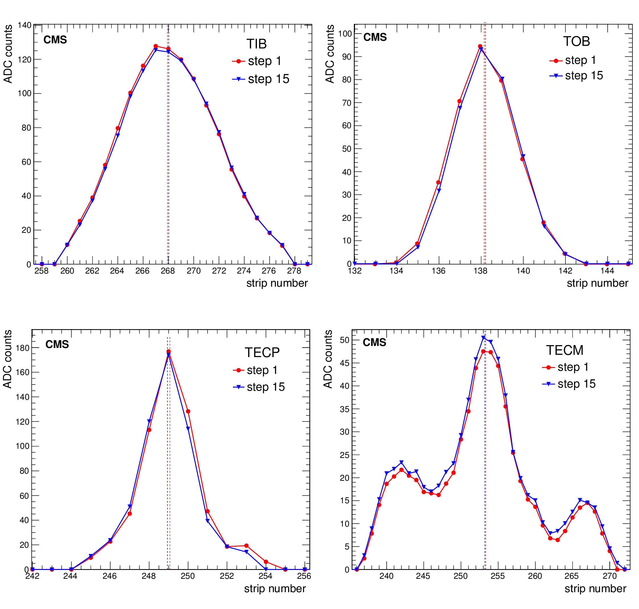
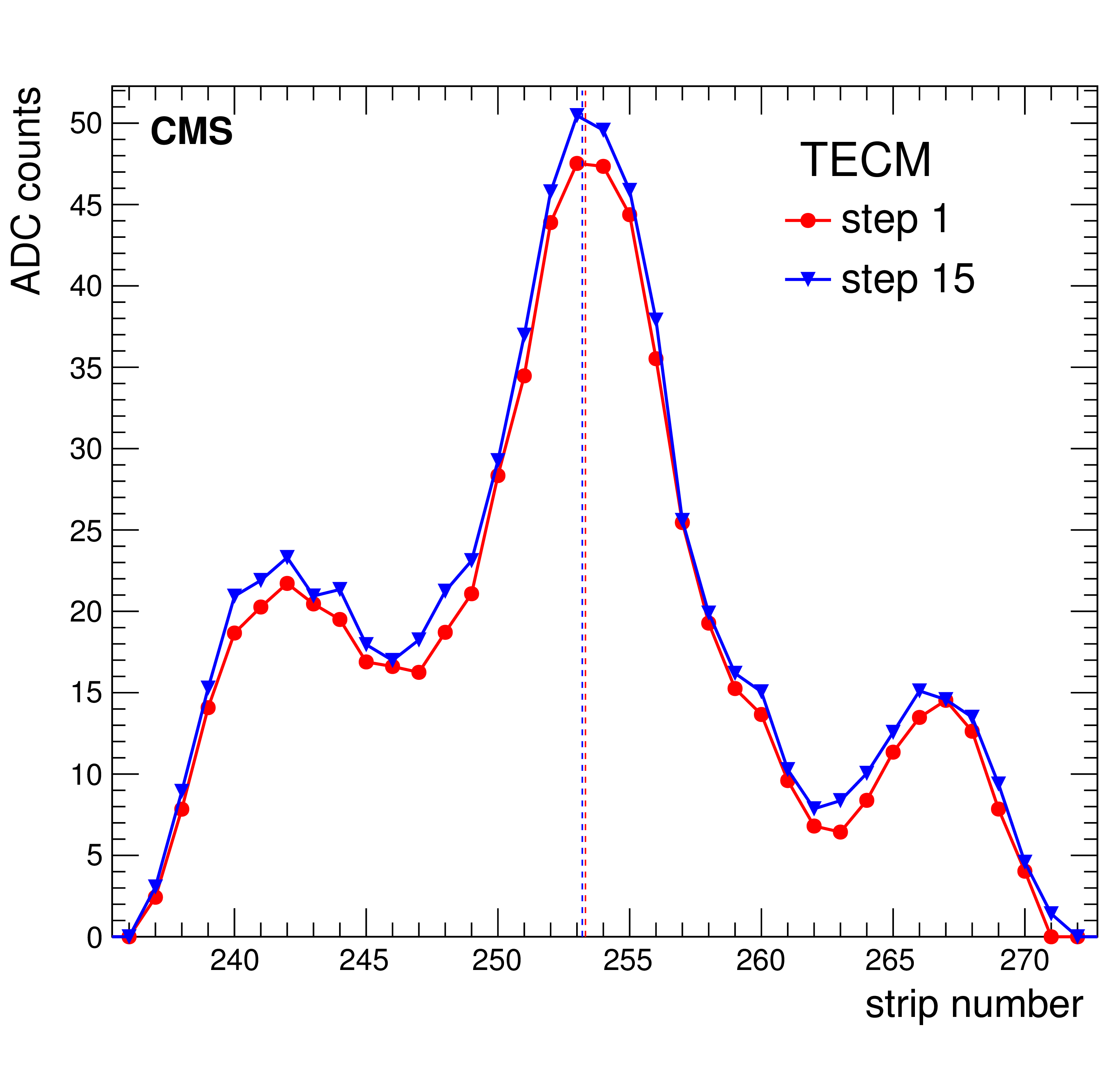
Examples of laser beam profiles (accumulated amplitude in ADC counts for 200 laser shots vs. strip number) in the TIB, TOB, TECP, and TECM modules, obtained in two different acquisition steps. The vertical dashed line shows the reconstructed laser spot position. In the TECM, two lower diffractive peaks are visible as mentioned in the text. |
png pdf |
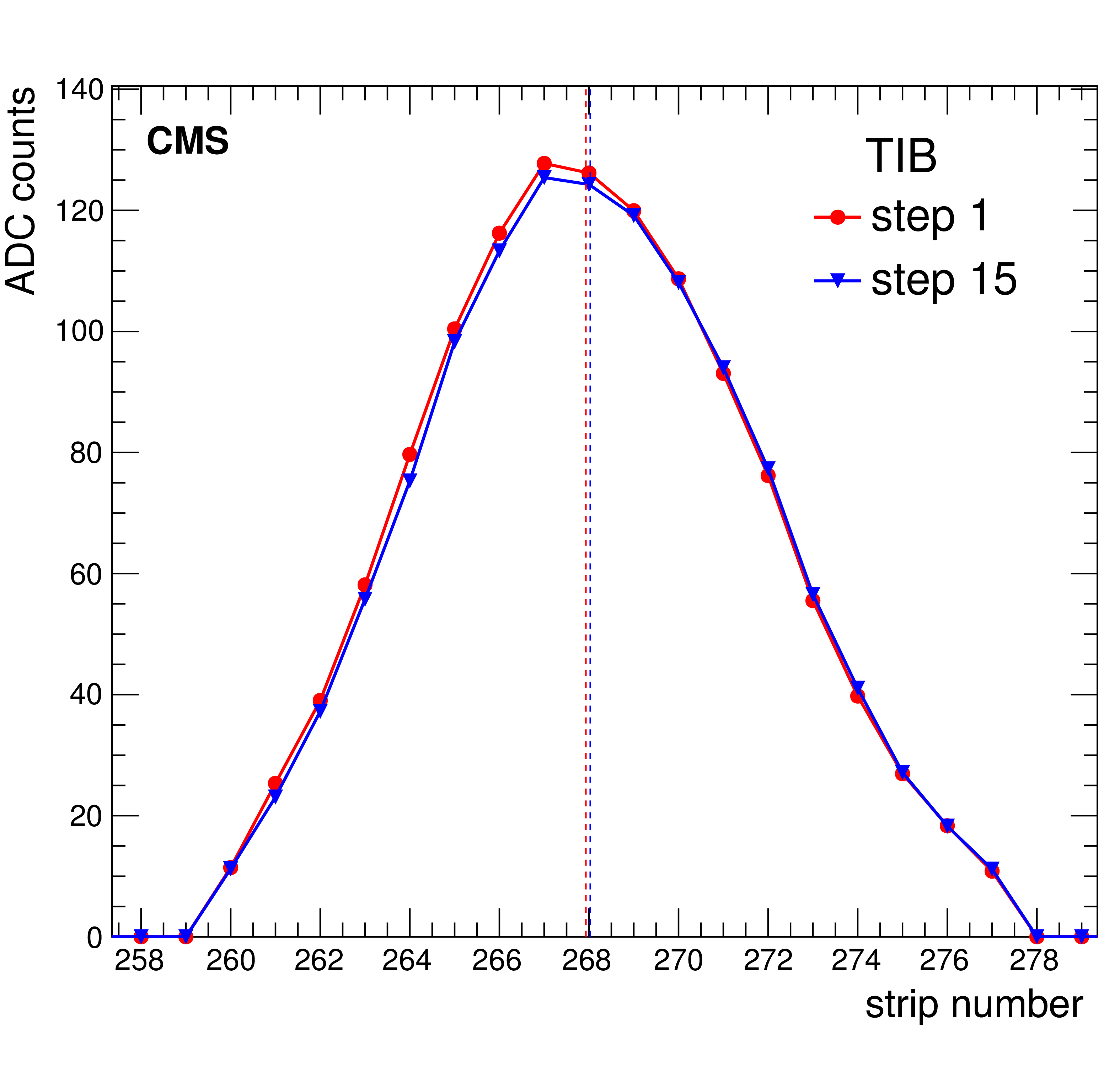
Figure 5-a:
Example of laser beam profile (accumulated amplitude in ADC counts for 200 laser shots vs. strip number) in the TIB, obtained in two different acquisition steps. The vertical dashed line shows the reconstructed laser spot position. |
png pdf |
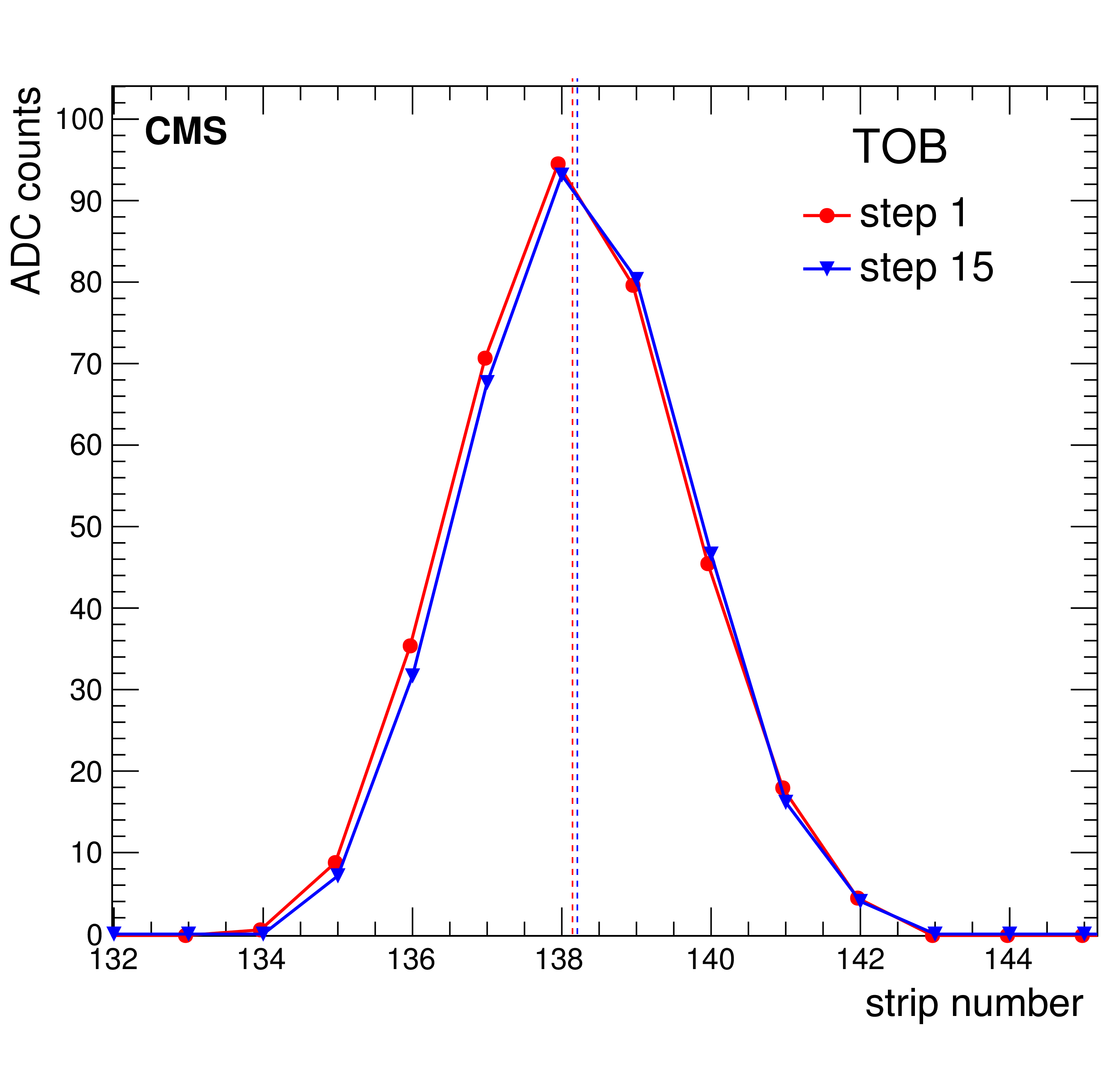
Figure 5-b:
Example of laser beam profile (accumulated amplitude in ADC counts for 200 laser shots vs. strip number) in the TOB, obtained in two different acquisition steps. The vertical dashed line shows the reconstructed laser spot position. |
png pdf |
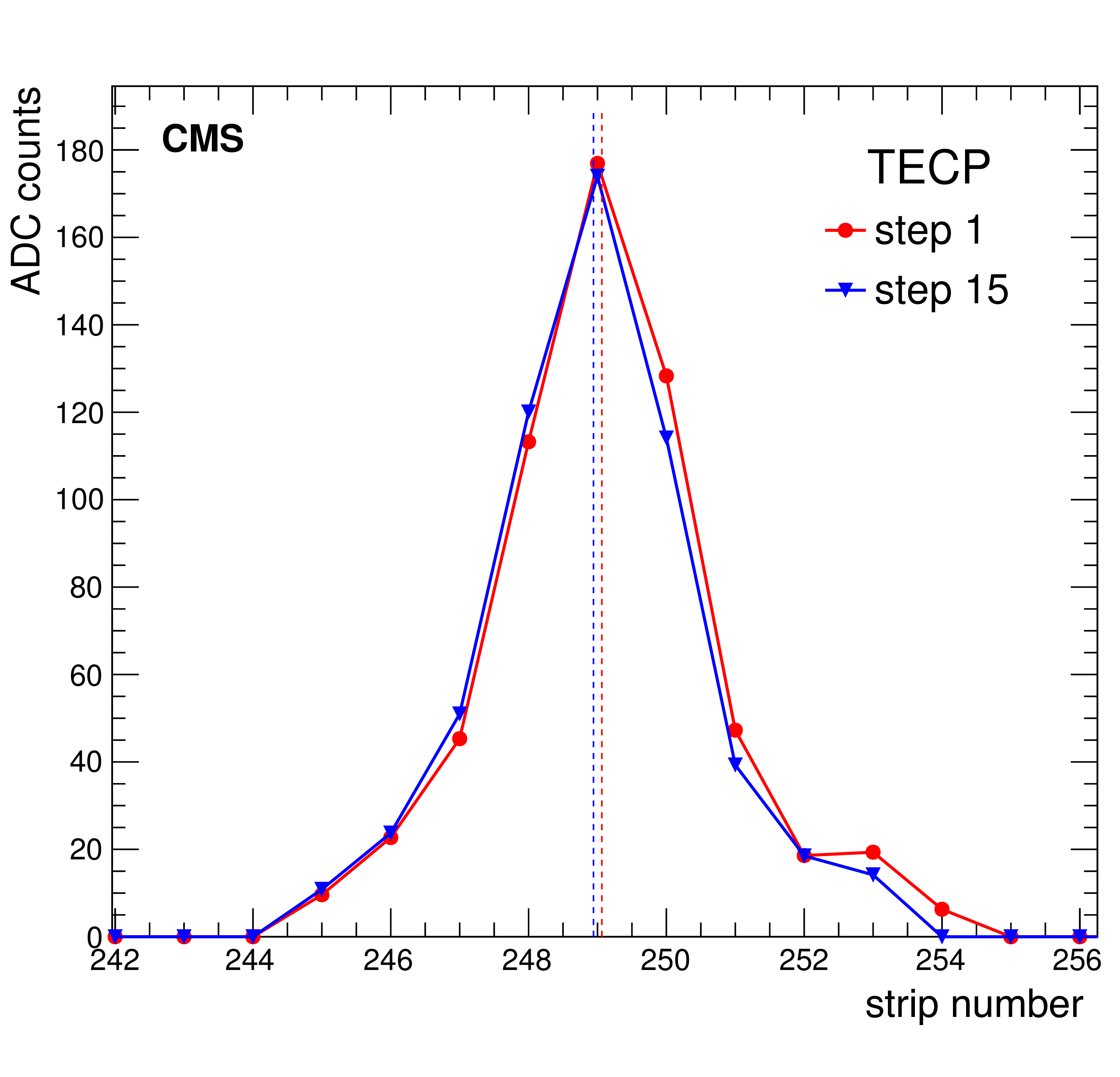
Figure 5-c:
Example of laser beam profile (accumulated amplitude in ADC counts for 200 laser shots vs. strip number) in the TECP, obtained in two different acquisition steps. The vertical dashed line shows the reconstructed laser spot position. |
png pdf |
Figure 5-d:
Example of laser beam profile (accumulated amplitude in ADC counts for 200 laser shots vs. strip number) in the TECM, obtained in two different acquisition steps. The vertical dashed line shows the reconstructed laser spot position. Two lower diffractive peaks are visible as mentioned in the text. |
png pdf |
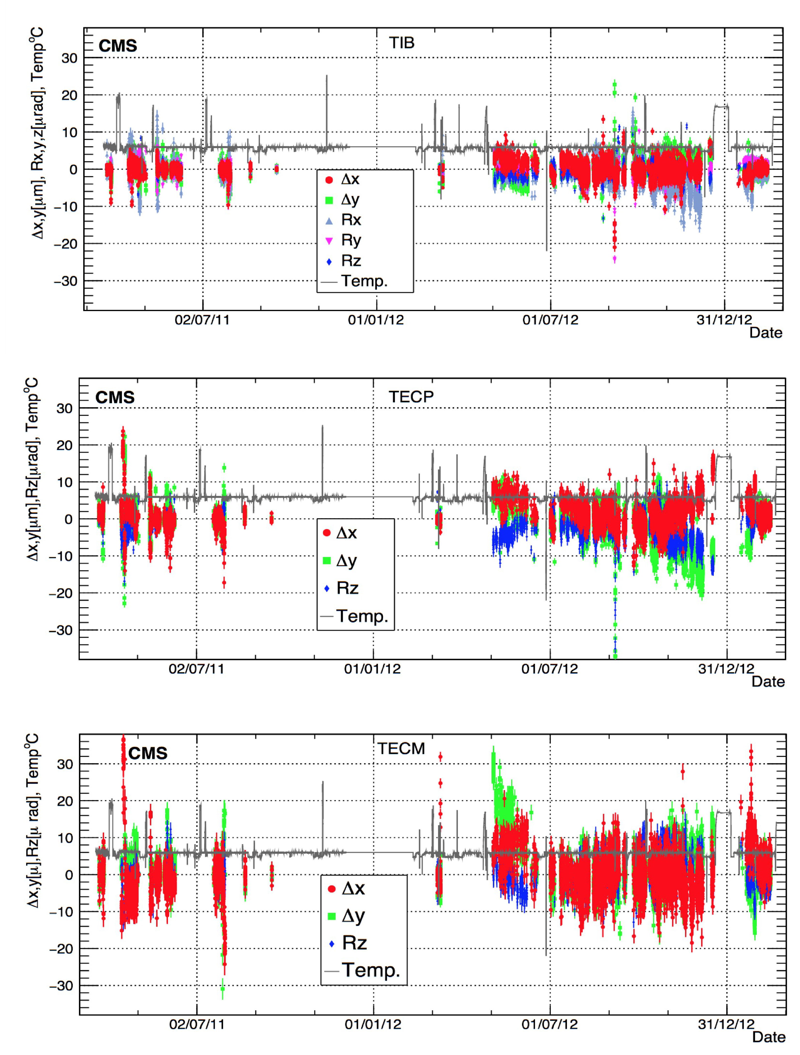
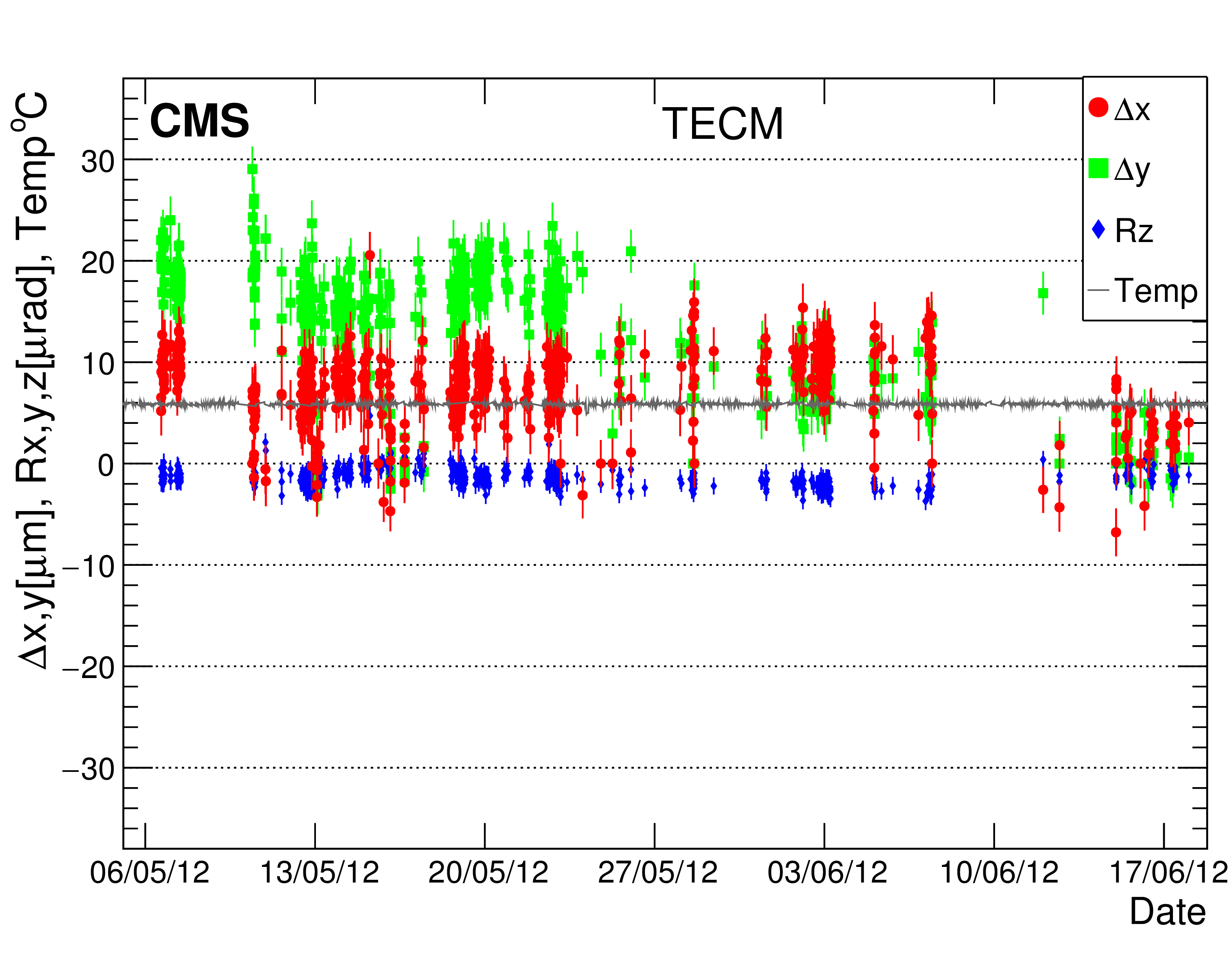
Figure 6:
Stability of TIB, TECP, and TECM alignment parameters during 2011-2013 data taking. The black line is the temperature of the cooling liquid in the return circuit. |
png pdf |
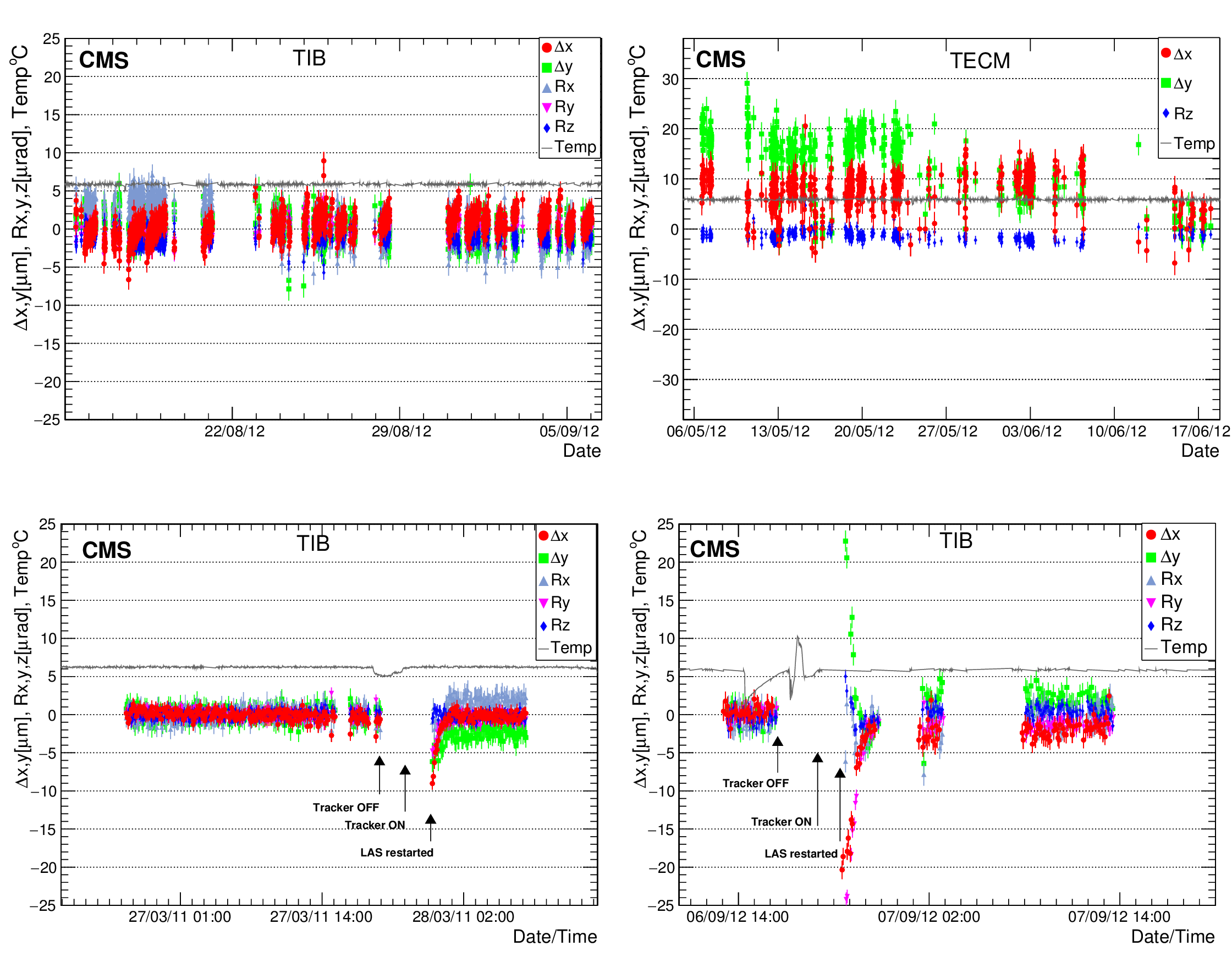
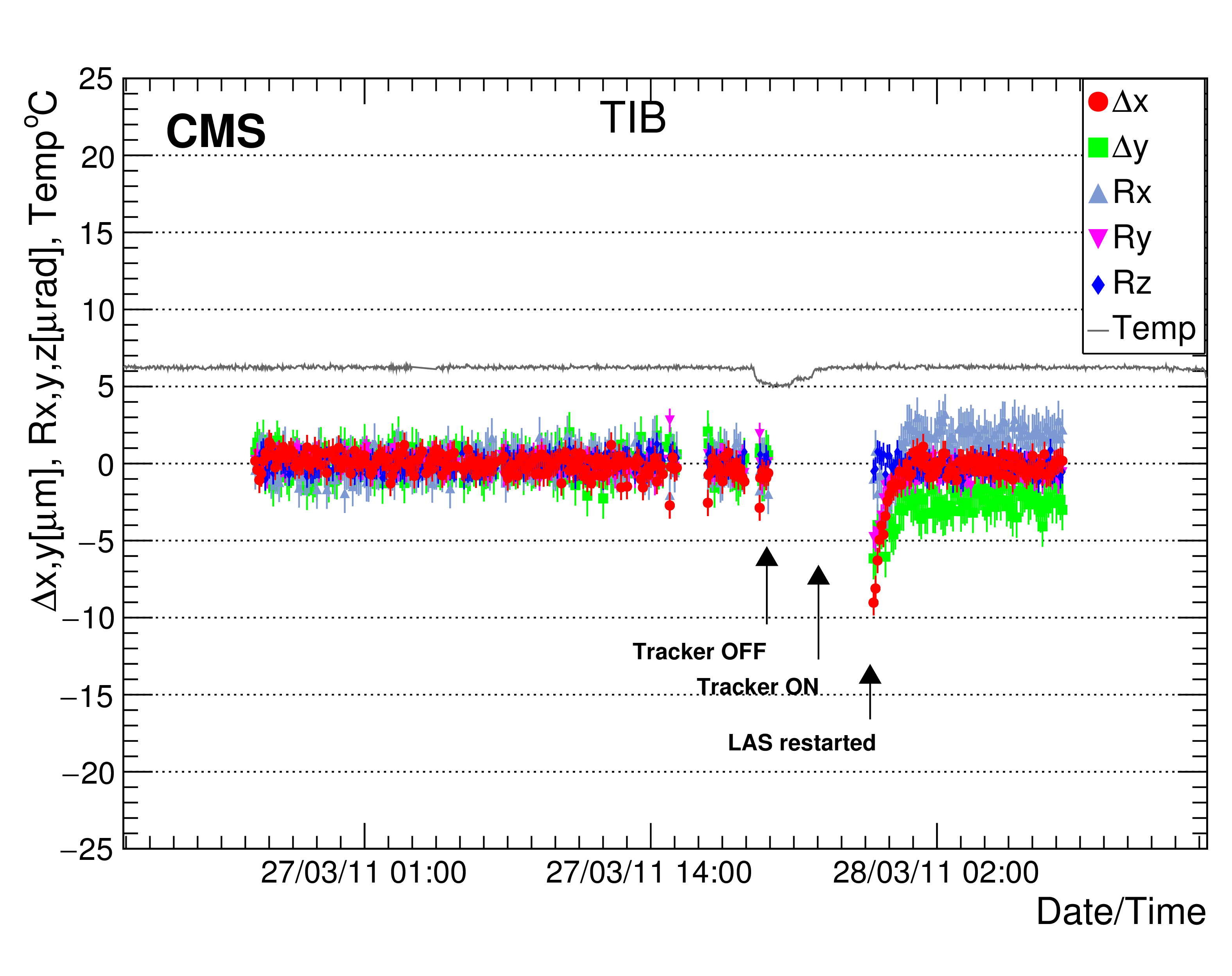
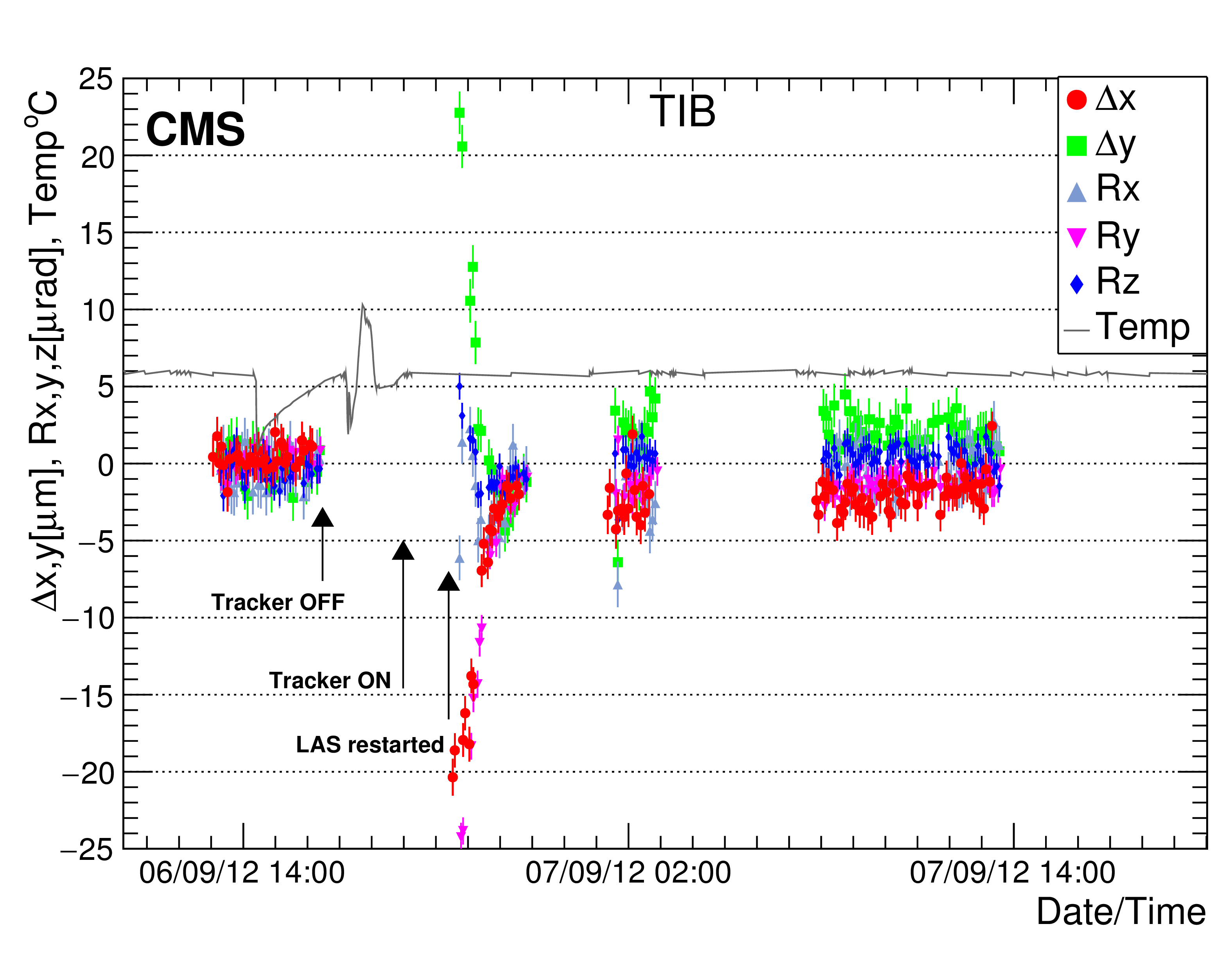
Figure 7:
Expanded view of the tracker alignment stability for selected time intervals. Upper left: TIB parameters during weeks of operation at stable temperature. Upper right: Variations of TECM parameters at stable temperature. Bottom left: Variations of TIB parameters after a power trip. Bottom right: TIB parameters after cooling plant shutdown and recovery. |
png pdf |
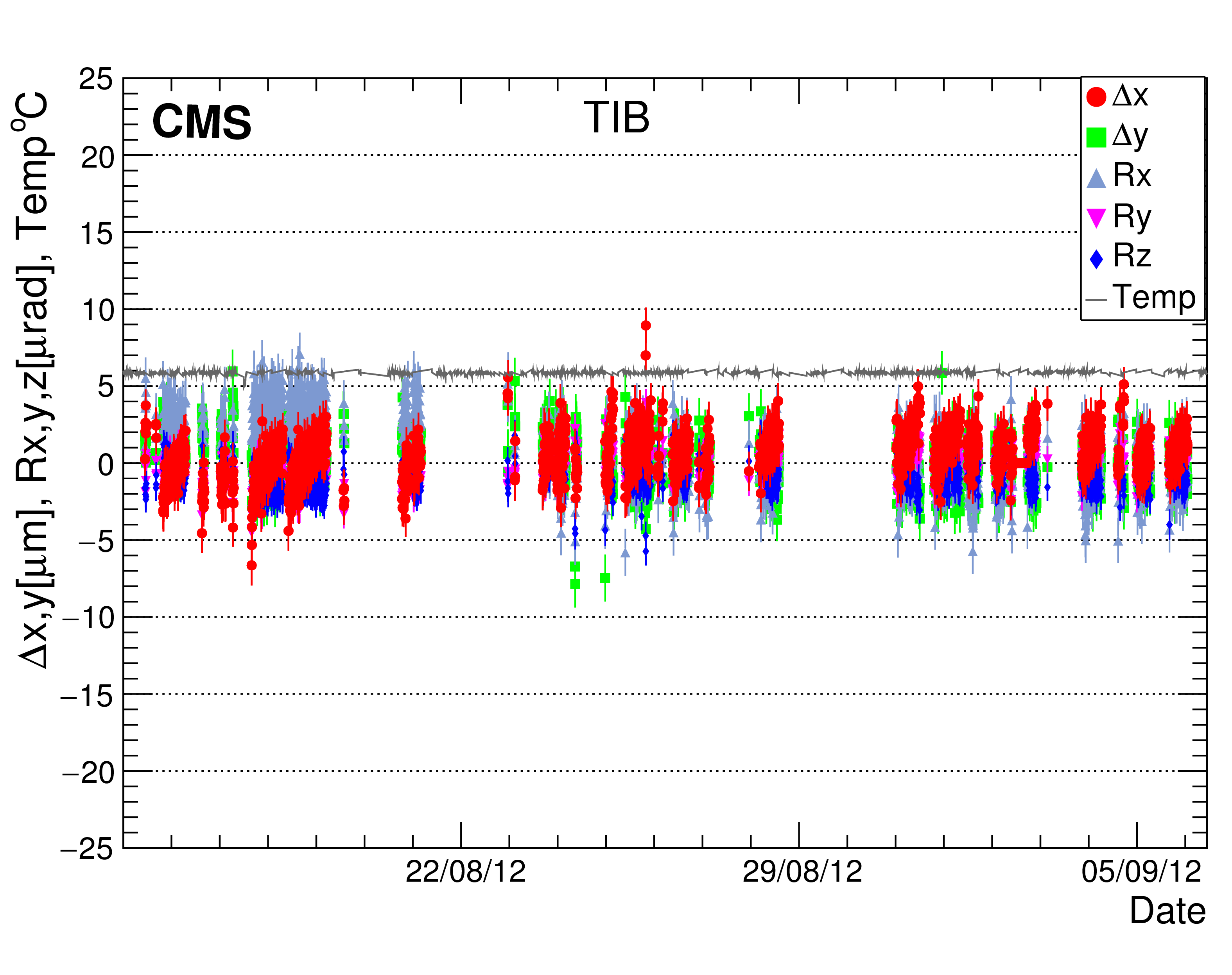
Figure 7-a:
Expanded view of the tracker alignment stability for selected time intervals: TIB parameters during weeks of operation at stable temperature. |
png pdf |
Figure 7-b:
Expanded view of the tracker alignment stability for selected time intervals: Variations of TECM parameters at stable temperature. |
png pdf |
Figure 7-c:
Expanded view of the tracker alignment stability for selected time intervals: Variations of TIB parameters after a power trip. |
png pdf |
Figure 7-d:
Expanded view of the tracker alignment stability for selected time intervals: TIB parameters after cooling plant shutdown and recovery. |
png pdf |
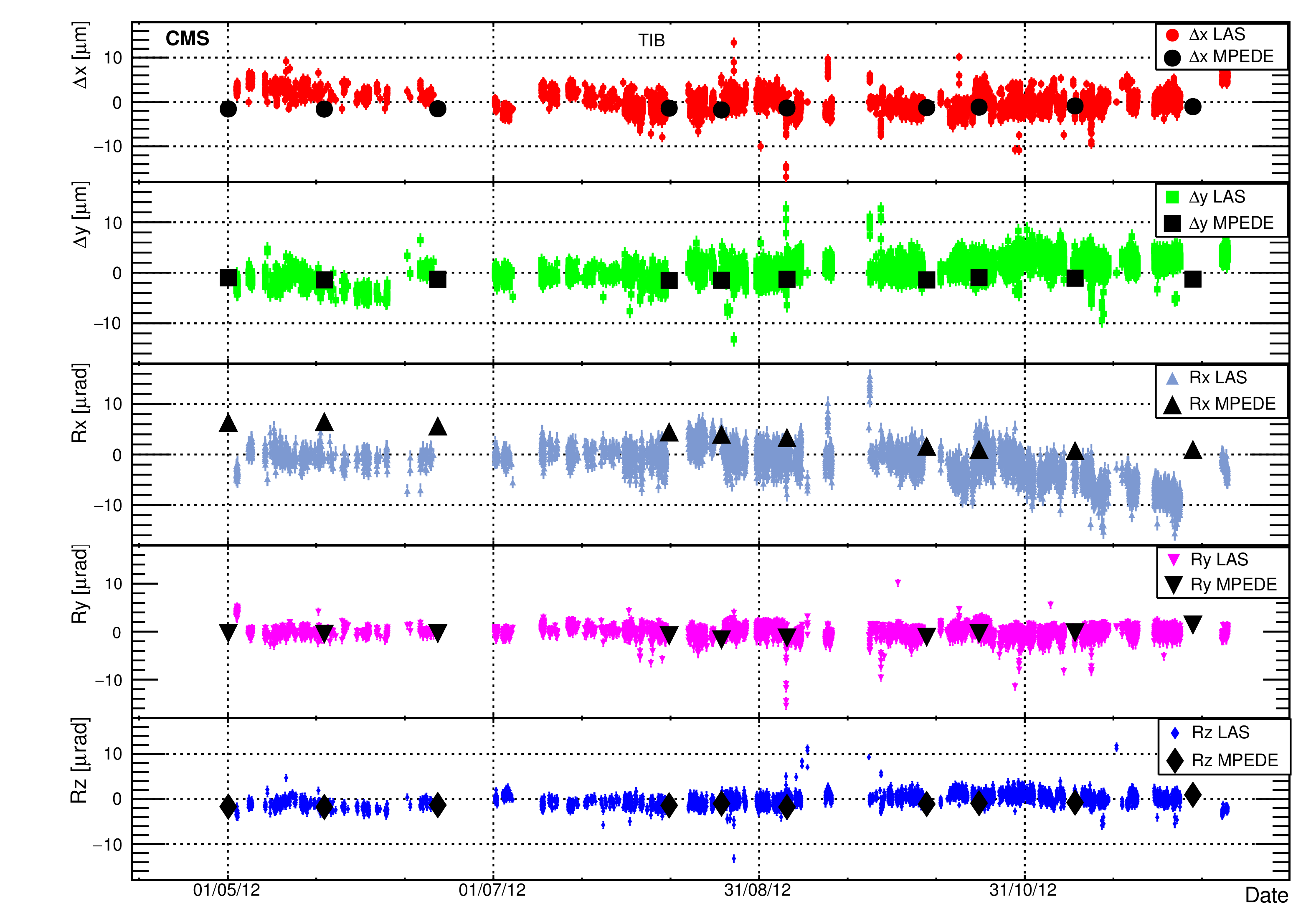
Figure 8:
Comparison of the TIB alignment parameters reconstructed with LAS data and calculated with {millepede} from measured particle tracks. |
png pdf |
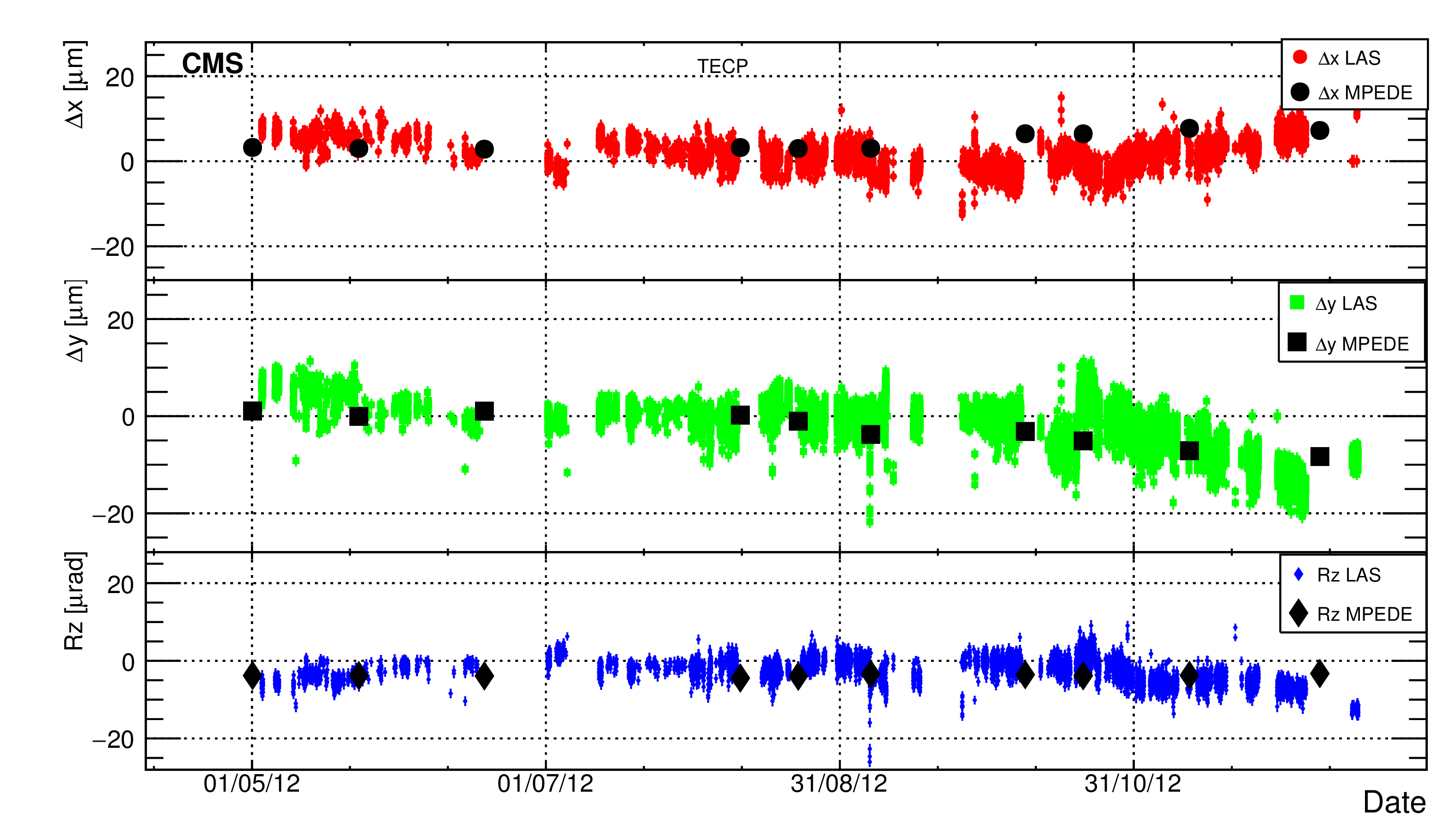
Figure 9:
Comparison of TECP alignment parameters measured with LAS and calculated with {millepede} from measured particle tracks. |
png pdf |
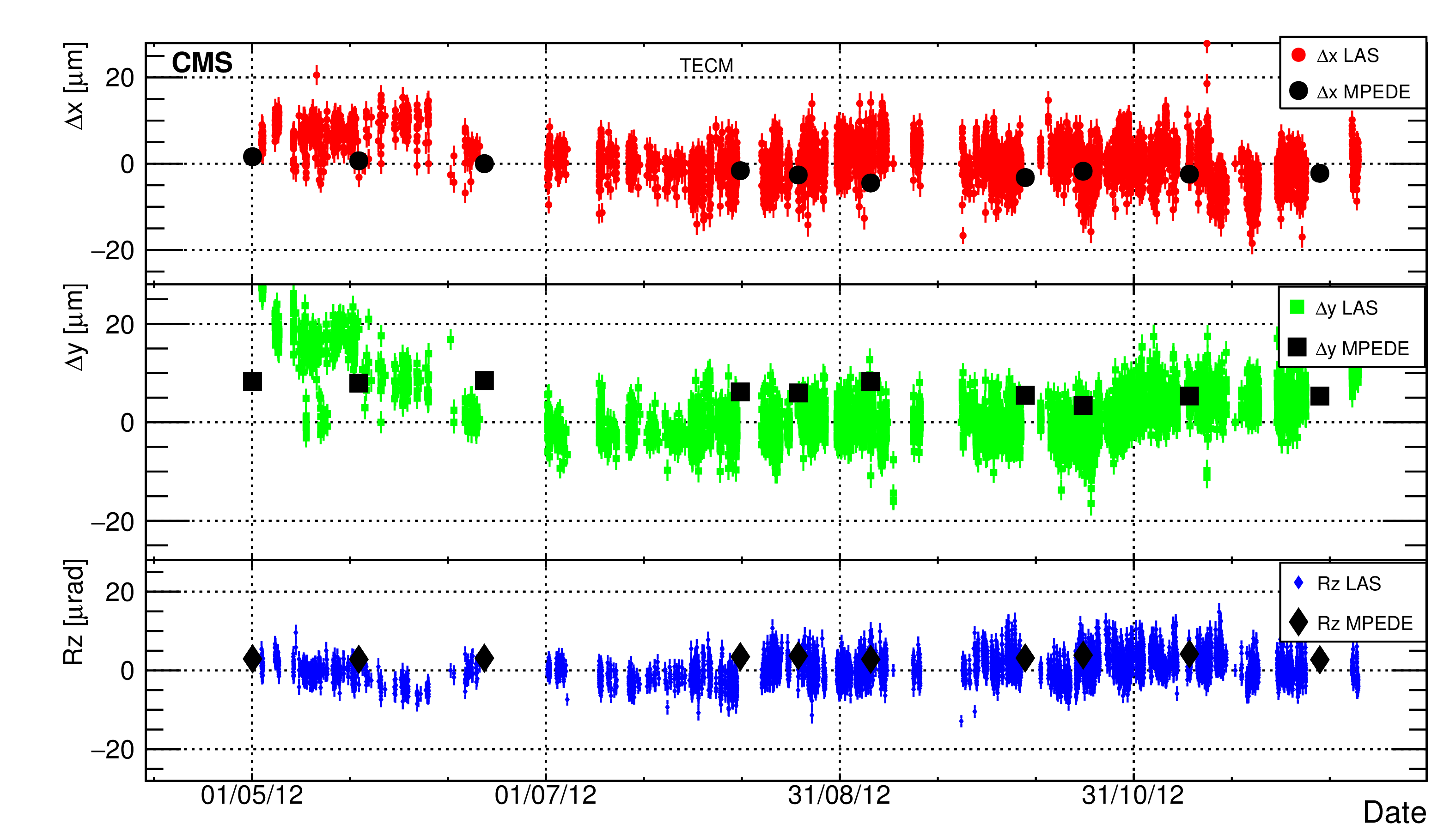
Figure 10:
Comparison of TECM alignment parameters measured with LAS and calculated with {millepede} from measured particle tracks. |
png pdf |
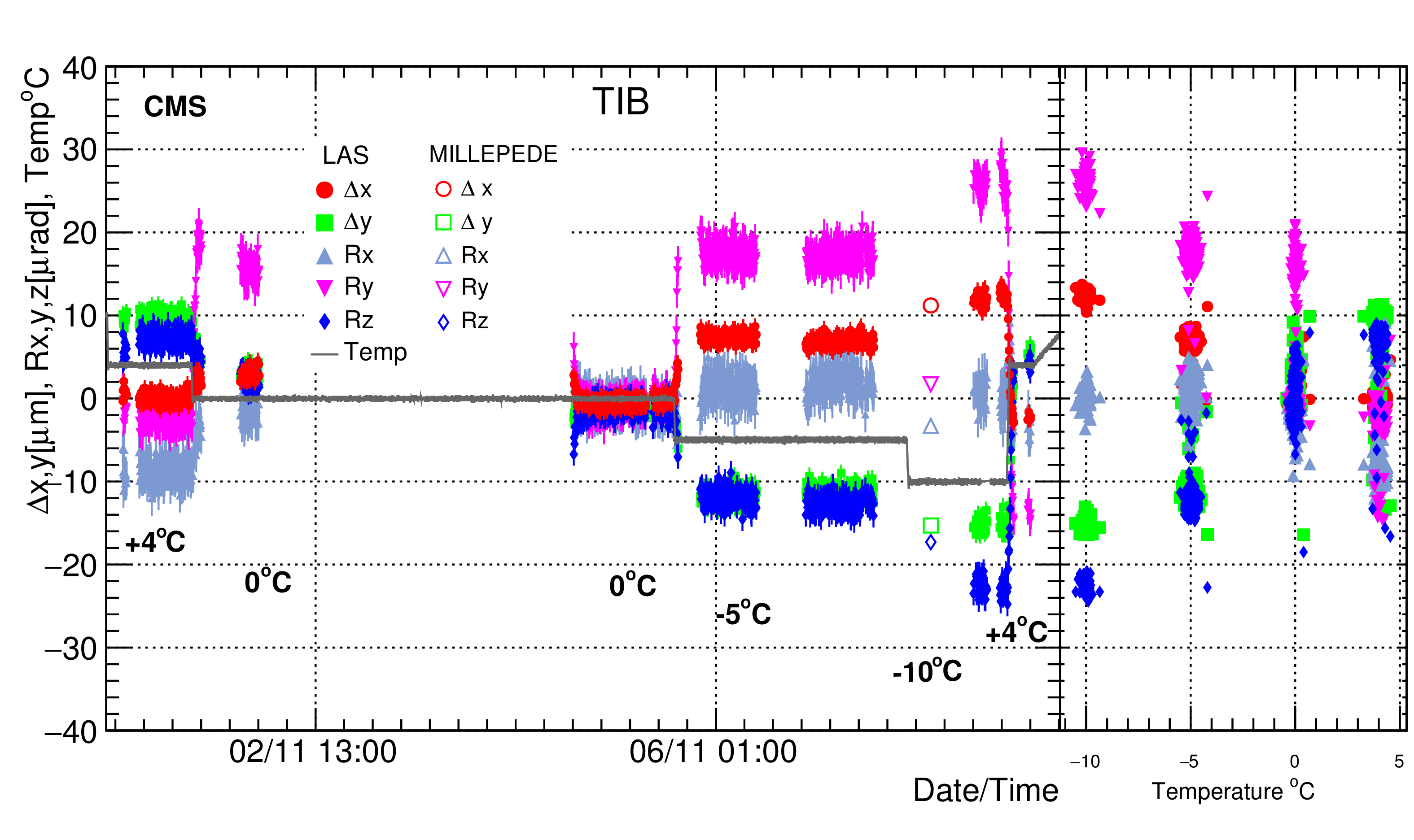
Figure 11:
Evolution of the TIB alignment parameters calculated with LAS during tracker thermo-cycling $+4\to 0 \to -5\to -10\to +4^\circ $C. The {millepede} points from cosmic ray muons are shown as open markers for the $0\to -10^\circ $C transition. |
| Tables | |
png pdf |
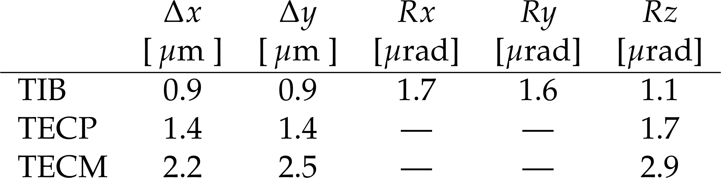
Table 1:
Stability of alignment parameters using LAS measurements obtained during periods of operation at a fixed temperature. |
| Summary |
| The mechanical stability of the CMS tracker was successfully monitored during the period 2011-2013 using a dedicated laser alignment system and particle tracks from collisions and cosmic ray muons. During the operation at stable temperatures, the variations of the alignment parameters were less than 30 $\mu$m and, in addition, larger changes were found to be related to temperature variations. These temperature-related displacements of the tracker subdetectors are of the order of 2 $\mu$m/$^\circ$C and are largely eliminated when the temperature is restored to its original value.The results presented in this study have been crucial for the CMS tracker operation in cold conditions. They have established that major mechanical displacements do not take place, and have shown the importance of monitoring the temperature within the detector volume. The observed behaviour of the tracker components under various conditions reported here provides guidance for future upgrades of the CMS tracking system. |
| References | ||||
| 1 | CMS Collaboration | Description and performance of track and primary-vertex reconstruction with the CMS tracker | JINST 10 (2014) P10009 | CMS-TRK-11-001 1405.6569 |
| 2 | CMS Collaboration | The CMS experiment at the CERN LHC | JINST 3 (2008) S08004 | CMS-00-001 |
| 3 | CMS Collaboration | The CMS tracker: addendum to the Technical Design Report | CMS Technical Design Report CERN-LHCC-2000-016 | |
| 4 | CMS Collaboration | Alignment of the CMS silicon tracker during commissioning with cosmic rays | JINST 5 (2010) T03009 | CMS-CFT-09-003 0910.2505 |
| 5 | CMS Tracker Collaboration | Alignment of the CMS silicon strip tracker during stand-alone commissioning | JINST 4 (2009) T07001 | 0904.1220 |
| 6 | CMS Collaboration | Alignment of the CMS Tracker with LHC and cosmic ray data | JINST 9 (2014) P06009 | CMS-TRK-11-002 1403.2286 |
| 7 | V. Blobel, C. Kleinwort, and F. Meier | Fast alignment of a complex tracking detector using advanced track models | Comp. Phys. Com. 182 (2011) 1760 | 1103.3909 |
| 8 | V. Blobel | Software alignment for tracking detectors | NIMA 566 (2006) 5 | |
| 9 | B. Wittmer et al. | The laser alignment system for the CMS silicon microstrip tracker | NIMA 581 (2007) 351 | |
| 10 | ALEPH Collaboration | Monitoring the stability of the ALEPH vertex detector | NPPS 78 (1999) 301 | physics/9903031 |
| 11 | ZEUS Collaboration | The optical alignment system of the ZEUS microvertex detector | NIMA 572 (2006) 325 | 0808.0836 |
| 12 | AMS-02 Collaboration | The AMS-02 tracker alignment system for 3D position control with artificial laser generated straight tracks | NIMA 572 (2006) 325 | |
| 13 | CMS Collaboration | Aligning the CMS muon chambers with the muon alignment system during an extended cosmic ray run | JINST 5 (2010) T03019 | CMS-CFT-09-017 0911.4770 |
| 14 | CDF Collaboration | The RASNIK real-time relative alignment monitor for CDF inner tracking detectors | NIMA 506 (2003) 92 | hep-ex/0212025 |
| 15 | ATLAS Collaboration | The Optical Alignment System of the ATLAS Muon Spectrometer Endcaps | JINST 3 (2008) P11005 | |
|
|
Compact Muon Solenoid LHC, CERN |
|

|

|

|

|

|